
Understanding Peristaltic Pump Head
Separate suction lift, discharge elevation, line loss, and pressure capability when reviewing a peristaltic pump application.
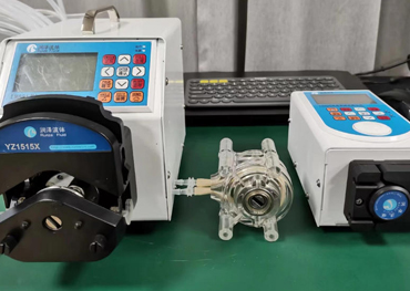
The word head is used in two ways around peristaltic pumps: it can mean the mechanical pump-head assembly that compresses the tubing, or the pressure requirement created by liquid elevation and line resistance. Keep those meanings separate during selection.
Peristaltic pumps are positive-displacement devices, but their practical pressure and suction capability depends on tubing recovery, occlusion, speed, fluid properties, and the installed system.
Separate static elevation from line loss
Static head comes from the vertical difference between fluid surfaces or the pump and the outlet. Dynamic loss comes from tubing length, internal diameter, fittings, valves, filters, viscosity, and flow velocity. Both contribute to the operating point.
Suction-side requirements deserve special attention because the tubing must reopen and draw fluid after roller compression. Excessive lift, restriction, viscosity, or speed can reduce refill and cause unstable flow even when the discharge side appears acceptable.
Pressure changes delivered volume
As discharge resistance increases, compliant tubing expands and recovery behavior changes. Internal slip at the occlusion region may also increase. The resulting flow can differ from an open-discharge catalog value.
Do not close or block the outlet during normal operation unless the system is designed for it. Define pressure protection, alarm behavior, and tubing containment from the current product limits and the hazard analysis.
Test the operating envelope
Measure flow at the minimum and maximum expected liquid level, temperature, viscosity, filter condition, tube age, and speed. Include start-up and priming behavior as well as steady operation.
A useful test report records suction elevation, discharge elevation, line geometry, fluid, tubing, pump head, occlusion setting, speed, and measured pressure. Verify allowable values with the current datasheet and application conditions.
Engineering takeaways
- Distinguish mechanical pump head from hydraulic head.
- Calculate elevation and line resistance on both suction and discharge sides.
- Validate flow across the real pressure and tubing-life envelope.