
Why Peristaltic Pump Flow Rate Varies
Understand why nominal peristaltic pump flow changes with tubing, occlusion, pressure, speed, and service time.
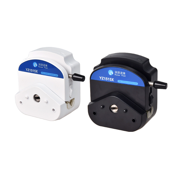
Peristaltic pump flow is created by repeated tube compression. The displaced volume per revolution depends on the tubing and pump head as an operating pair, so the same nominal speed does not guarantee the same delivery in every installation.
A useful investigation separates normal process variation from a selection, installation, or wear problem.
Variables that change displacement
Tubing inner diameter has a strong effect on volume per revolution, while wall thickness and material resilience influence how completely the tube reopens after a roller passes. Manufacturing tolerance, aging, temperature, and chemical exposure can all change the tube's response.
Occlusion also matters. Too little compression can allow slip or backflow; too much compression can increase motor load, heating, pulsation, and tubing fatigue. Use the pump-head and tubing combination specified for the equipment instead of assuming that a physically installable tube is suitable.
System resistance and fluid behavior
Suction lift, discharge elevation, filters, narrow fittings, long tubing, viscous liquid, and partially closed valves change the pressure required from the pump. As resistance rises, tubing recovery and internal slip can change actual flow. Entrained gas adds compressibility and can make short measurements unstable.
Speed changes may also affect tube refill. At high speed, a tube that has not fully recovered before the next roller pass can deliver less volume per revolution than a low-speed estimate suggests.
Create a controlled comparison
Use the same tubing lot, installed length, fluid, temperature, suction condition, outlet restriction, run time, and measurement method when comparing settings. Prime completely and allow the system to stabilize before recording data.
If flow drifts with service time, inspect the tubing at the roller track and compare a new segment under the same conditions. Catalog flow figures are reference values measured under stated conditions; verify the current manual and the actual application before setting acceptance limits.
- Record flow per revolution as well as flow per minute.
- Trend motor load, tubing hours, and calibration factor when available.
- Define a replacement rule before drift affects the process.
Engineering takeaways
- Treat tubing as part of the pumping mechanism.
- Control pressure, temperature, priming, and measurement time during tests.
- Recalibrate after changes to the fluid path or tubing condition.