
Syringe Pump Flow Rate Calculation: A Practical Engineering Method
Convert syringe geometry and actuator motion into a defensible flow estimate, then validate the result at the outlet.
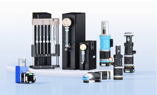
A syringe pump converts linear plunger movement into displaced liquid volume. The useful calculation therefore starts with syringe geometry and actual actuator motion, not only a motor speed shown in a controller.
The result is an engineering estimate. Seal friction, compliance, valve timing, trapped gas, backlash, and outlet pressure can change delivered flow, so a gravimetric or volumetric check remains part of commissioning.
Start with displaced volume
For a cylindrical syringe, piston area is A = pi x D squared / 4, where D is the effective internal diameter. If the plunger moves at linear speed v, theoretical flow is Q = A x v. Keep all dimensions in one unit system before converting the result to microliters per minute or milliliters per minute.
When the drive is pulse controlled, derive linear motion per pulse from the screw lead, transmission ratio, motor step angle, and microstep setting. Multiplying motion per pulse by piston area gives volume per pulse; multiplying again by pulse frequency gives theoretical flow.
- Use the effective syringe bore, not the external barrel diameter.
- Record screw lead and transmission ratio from the current product documentation.
- Check whether the controller value represents full steps, microsteps, or an internal speed unit.
Keep units and operating phases explicit
A common error is mixing millimeters, micrometers, seconds, and minutes in the same calculation. Write the conversion beside each variable and carry units through the equation. Also distinguish steady dispense motion from refill, valve switching, acceleration, and deceleration. A cycle-average flow can be lower than the flow during the active dispense stroke.
For discontinuous operation, calculate delivered volume per cycle and divide by the complete cycle time. If two pumps alternate to create continuous delivery, include the overlap and switching logic rather than simply doubling one pump's value.
Validate at the real outlet
Run the intended syringe, liquid, valve sequence, tubing, and pressure condition long enough to average short-term effects. Gravimetric measurement is often convenient when liquid density is known; direct volumetric collection can be used when density is uncertain.
Compare measured and theoretical delivery, calculate the correction factor, and save the test conditions with the result. Revalidate after a syringe, seal, valve, line geometry, or control parameter changes. Verify product-specific limits with the current datasheet and application conditions.
Engineering takeaways
- Calculate from effective piston area and verified linear motion.
- Include the complete pump cycle when average flow matters.
- Use outlet measurement to convert a theoretical value into a controlled process setting.