
Selecting Peristaltic Pump System Components
Select the drive, pump head, tubing, controls, and downstream hardware as one operating system rather than independent catalog items.
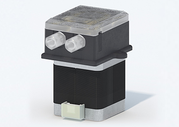
A peristaltic pump system includes the drive, pump head, tubing, fluid connections, controls, power, mounting, and downstream fluid path. Selecting these parts independently can create a combination that fits mechanically but misses the required operating point.
Use one requirements table and maintain traceable compatibility evidence for the complete configuration.
Select the drive from the duty cycle
Define speed range, continuous or intermittent duty, direction changes, acceleration, torque margin, number of channels, noise, environmental limits, power, and control interface. Determine whether the instrument needs local controls, analog input, digital start-stop, communication, dispensing modes, or fault feedback.
Do not assume that similar-looking drives expose the same control functions or duty rating. Confirm the exact model in current documentation.
Match the head and tubing
Choose a head that supports the required tubing sizes, channel count, loading method, roller configuration, pressure range, and maintenance access. Then compare approved tubing candidates for flow, material, temperature, pressure, fluid quality, and service life.
Keep head-to-drive and tube-to-head relationships explicit by model and part number. Physical attachment alone is not compatibility evidence.
Complete the fluidic and control design
Size fittings, check valves, filters, sensors, dampers, and outlet hardware from the pressure and flow budget. Control bend radius, dead volume, bubble traps, tube support, and service access in the enclosure.
Verify start-up, prime, normal run, dispense, reverse, stop, blockage, leak, communication loss, and power recovery. Calibrate the final assembly and define tubing replacement and post-service checks.
- Create a controlled BOM for every qualified configuration.
- Record unsupported or unverified combinations instead of assuming them.
- Review current manuals when any component revision changes.
Engineering takeaways
- Select the system from one duty-cycle and interface specification.
- Maintain exact drive-head-tubing compatibility evidence.
- Qualify the complete BOM through normal and fault sequences.