
Designing Low-Carryover Fluid Paths
Reduce carryover by controlling residual volume, interfaces, valve sequencing, wash chemistry, and verification methods across the complete flow path.
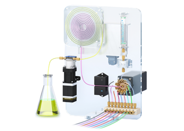
Carryover is residual material from one sample or reagent that appears in a later fluid segment. It is a system property created by geometry, surfaces, interfaces, sequencing, wash conditions, and measurement sensitivity, not a label that one component can guarantee by itself.
Low-carryover design begins by mapping where liquid can remain and how each operating sequence displaces it.
Reduce retained volume and difficult interfaces
Shorten unnecessary line length, avoid abrupt internal steps, minimize dead legs, and choose compatible bore transitions. Review valve cavities, syringe ports, fitting shoulders, tees, manifolds, sensors, and outlet geometry for regions with weak exchange.
Surface chemistry matters as well as volume. Adsorption, poor wetting, bubbles, particles, and protein films can retain material even in a small cavity. Select wetted materials from the fluid and cleaning requirements and verify them experimentally.
Design the sequence and wash together
Document valve state and pump direction for aspiration, transfer, dispense, wash, air gap, and drain steps. A component architecture such as the PS-10 system may support separation of fluid paths in suitable applications, but actual carryover depends on the configured tubing, valves, sequence, liquids, and maintenance.
Select wash volume, flow direction, contact time, number of cycles, and chemistry from measured removal behavior. More wash volume is not always equivalent to better exchange if a trapped region is never reached.
Measure carryover at the required sensitivity
Use a high-concentration sample followed by defined blanks and measure the marker with a method sensitive enough for the application. Report the calculation, sequence, volumes, time, and detection limit so results can be reproduced.
Challenge worst-case fluids, concentrations, idle times, temperatures, tube ages, and maintenance states. Confirm current PS-10 and other component information with the latest product documentation and application review.
- Distinguish sample carryover from instrument background and reagent contamination.
- Include bubbles and incomplete priming in the fault analysis.
- Define cleaning verification and replacement criteria for wetted parts.
Engineering takeaways
- Treat carryover as a complete flow-path and sequence problem.
- Minimize retained regions and verify that the wash reaches them.
- Qualify with a reproducible analytical method and worst-case fluids.